AYANEO 2 / GEEK Powerful Heat Dissipation Module Upgrade Guide
This guide provides instructions on upgrading the internal cooling system of the AYANEO 2 and AYANEO GEEK handheld consoles to the “3+1” three copper tube heat dissipation module.
Tools & Parts Needed
- Replacement Part: AYANEO 2 / GEEK Heat Dissipation Upgrade Kit (3+1 Module)
- Tools:
- Recommended: Anti-static gloves or wrist strap
Precision screwdriver set Non-conductive prying tool (disassembly slice) * Tweezers
> ### ⚠️ Safety Warnings > Power Off: Ensure the device is fully powered off and unplugged from any power source before beginning. > Battery Care: The battery is sensitive; do not puncture, bend, or subject it to physical stress. > Static Electricity: Use anti-static protection to prevent ESD (Electrostatic Discharge) damage to the motherboard components. > Fragile Components: Ribbon cables and connectors are highly fragile. Apply minimal force and use appropriate tools to prevent tearing.
—
Disassembly & Upgrade Steps
- Disassemble the case: Use a precision screwdriver to remove the outer case screws. Gently use a non-conductive disassembly slice to pry open the housing along the seam.
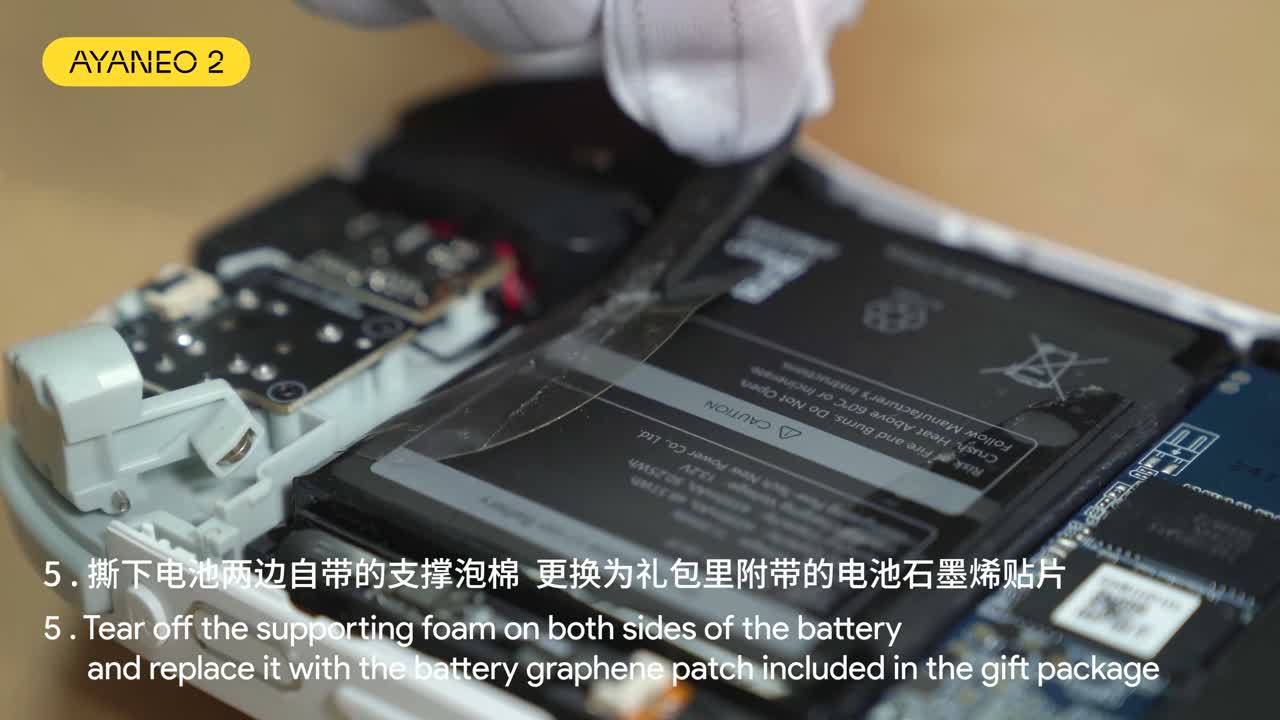
- Replace battery graphene patches: Remove the original supporting foam located on both sides of the battery. Carefully apply the new graphene patches provided in the upgrade kit to the same locations.
- Remove fan bracket: Carefully unfasten the fan bracket. Ensure no surrounding ribbon cables are snagged or damaged during removal.
- Apply thermal grease: Clean the existing residue from the CPU surface and apply a small, even amount of fresh thermal grease.
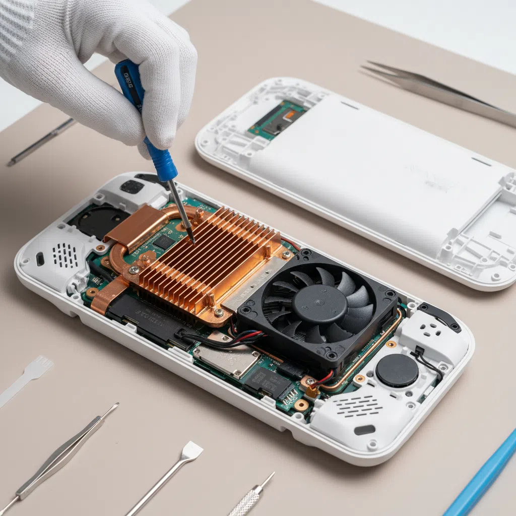
- Install the cooling module: Carefully align the new 3+1 copper tube module onto the motherboard, ensuring it seats perfectly over the CPU.
- Close the back cover: Replace the housing and secure it with the outer screws, ensuring all internal components are seated correctly and no cables are pinched.
[Visual Reference: Close-up of screwdriver removing individual case screws / window-01-t00575-003.jpg]*
[Visual Reference: Macro shot of thermal paste application and thermal silica pad placement / window-03-t02225-003.jpg]*
[Visual Reference: Securing the back cover and replacing all outer screws / window-05-t04625-003.jpg]*
—
Troubleshooting & Notes
- Thermal Management: If the device experiences thermal throttling post-upgrade, verify that the thermal pads are making full contact with the heat sink and that no protective plastic films were left on the pads.
- Boot Issues: If the device fails to power on after reassembly, double-check that the battery connector is fully seated and that no ribbon cables were dislodged during the process.
—
Follow-up Capture Needs
The following steps require additional documentation to ensure clarity:
- Connector Disconnects: The process for safely releasing internal ribbon cables and the battery connector requires high-resolution capture.
- Screw Mapping: Detailed documentation of screw locations and types (lengths) is needed, as the current footage lacks this granularity.
- Heatsink Alignment: A macro, stable shot of the 3+1 module seating process is required to confirm proper orientation.
—